77. UML class diagrams#
When reasoning about object oriented design UML class diagrams serve as a particularly efficient tool. Even if only informally. Having a good understanding of UML class diagram notation is essential if we are to be able to eventually understand object oriented design patterns.
Important
UML class diagrams help visualize the design and structure of a system, allowing us to reason about designs efficiently and without getting bogged down by unnecessary details.
See also
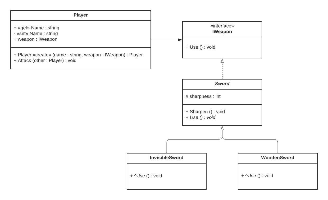
In the UML class diagram below we see a class called Player which ‘has’ an IWeapon which is an interface. The abstract class Sword is an implementation of the interface ISword and the classes InvisibleSword and WoodenSword both inherit from Sword. In the diagram we can also see examples of fields (weapon), properties (Name), access modifiers (+, -, #), methods (Attack), constructors (Player), abstract members (Use in Sword), and overriding (Use in WoodenSword).
The code underlying this system might look something like what we have below.
Show code cell source
interface IWeapon
{
    void Use();
}

public abstract class Sword : IWeapon
{
    protected int sharpness = 1;

    public void Sharpen()
        => sharpness++;

    public abstract void Use();
}

public class WoodenSword : Sword
{
    public override void Use()
        => Console.WriteLine($"Used Wooden Sword with sharpness {sharpness}.");
}

public class InvisibleSword : Sword
{
    public override void Use()
        => Console.WriteLine($"Used Invisible Sword with sharpness {sharpness}.");
}

class Player
{
    public string Name { get; private set; }
    private IWeapon weapon;

    public Player(string name, IWeapon weapon)
    {
        this.Name = name;
        this.weapon = weapon;
    }

    public void Attack(Player other)
    {
        Console.WriteLine($"{Name}'s turn.");
        weapon.Use();
    }
}
Let us now briefly discuss how to model most important object oriented concepts in UML class diagrams one by one. Remember to refer back to the image for visual representations.
Tip
There’s a lot of variation in UML class diagrams that you’ll find in the wild. If you’re not following the standard, pick a syntax and stick to it. Understandability is key.
Classes#
To depict a class in a UML class diagram we draw a rectangle (known in UML as an ‘entity’) with three sections. In the top section we write the ‘identifier’ (meaning the name) of the class. In the middle section we write the ‘attributes’ of the class. In the bottom section we write the ‘operations’ of the class.
Attributes are essentially instance variables (which in C# means that they are either instance fields or instance properties). Operations on the other hand are instance methods. The attributes (instance variables) and operations (instance methods) of a class are collectively referred to as the ‘members’ of the class.
Tip
To avoid cluttering the diagram, class members are often omitted, unless they are relevant for the discussion at hand.
Fields#
Fields are modeled as attributes. In the second section of an entity we write the name of the field, followed by a colon (:) and then the data type of the attribute. See, for example, the sharpness field in the Sword class.
Access modifers#
We can mark attributes or operations as public, private, or protected by prepending a plus sign (+), minus sign (-), or hash symbol (#), respectively. See, for example, the protected field sharpness in Sword or the private field weapon in Player.
Properties#
Since UML class diagrams are language independent there is no specific support for the C# specific idea of properties.
One common way of modeling properties is by means of the «get» and «set» ‘stereotypes’. We define one UML attribute for the getter and one for the setter and then prepend the appropriate sterotype. See, for example, the Name property of the Player class.
Instance methods#
Instance methods are modeled as ‘operations’ which means that they are listed in the third section of a box. We can specify both the parameter list of an operation and the return type. See, for example, the Attack method in the Player class
Constructors#
Constructors should, according to the UML specification, be modeled by prepending the «Create» ‘stereotype’ to the member. In practice however, we often find diagrams where the constructor is implicit and simply has the same name and return type as the class. See, for example, the Player constructor in the diagram.
Composition#
In UML class diagrams we refer to object composition as ‘association’ and we draw it using an arrow.
The arrow points from the subclass to the superclass.
The arrow is pointing from the type that has a reference (i.e. the ‘composing’ object) to the type that it has a reference to (i.e. the ‘composed’ object).
We tend to refer to this as ‘has-a’ relationship.
See, for example, the arrow from the Player class to the IWeapon interface.
This refers to the weapon field in the Player class.
Tip
Classes that are in a ‘has-a’ relationship (meaning association) are conventionally drawn next to eachother horizontally, while classes that are in an ‘is-a’ relationship (meaning generalization or realization) are positioned vertically so that the subtype is below the supertype. This is a convention and not a rule.
See also
UML divides the concept of association into two types that they call ‘aggregation’ and ‘composition’. The term ‘composition’, in UML, does not mean the same thing as object composition. We won’t discuss the two types of association in detail in this book. For more reading, please see the Wikipedia page on UML class diagrams or the UML specification.
Interfaces#
Interface implementation is, in UML, called ‘realization’ and is depicted using a dashed line with a hollow arrow head.
The arrow points from the implementation to the interface.
An interface is an entity but where the ‘classifier’ «interface» is added above the identifier.
See, for example, interface IWeapon and its relationship with the abstract class Sword.
Implementations are conventionally drawn ‘below’ interfaces.
Whether or not to include (meaning: repeat) the members of the interface in the implementation varies depending on who you ask.
Neither leads to a loss of information since if the implementor implements the interface then it must by definition implement all its members.
Inheritance#
Inheritance is, in UML, called ‘generalization’ (or sometimes simply ‘inheritance’) and is depicted using a solid line with a hollow arrow head.
Subclasses are conventionally drawn ‘below’ superclasses.
To differentiate inherited or overridden members apart from hidden members, inherited or overridden members are either not repeated in the subclass or the caret symbol (^) is prepended to their name.
There is no standard syntax for telling overriding apart from inheriting.
Important
Association (meaning object composition), realization (meaning interface implementation), and generalization (meaning inheritance), are all directed relationships. For example, just because I consider you my friend, doesn’t mean that you consider yourself mine. Similarly, all cats are animals, but not all animals are cats.
Abstract#
Abstract classes and members are denoted by writing the classifier in italics.
If the font does not permit italics, the specification states that we add the textual annotation {abstract} after or below.
See, for example, the abstract class Sword and the abstract method Use.